Actuator Accessibility
Cycloidal Drive
An exercise into a more accessible actuator design for the modified Solo12
Solo12 has a very compact and lightweight design which imposes dimensional constraints on the choice of drive. All joints, except the knee, can be directly driven, reducing the need to source AT3 timing belts, pulleys and associated hardware.
Alternative drive mechanism are explored in order to find a more accessible approach to quadruped joints i.e. in this case the cycloidal drive is fully 3D printed and only requires standard bearings.
A FDM 3D printed cycloidal drive was initially designed to fit in a 5cmx5cmx5cm bounding box. At this scale, small dimensional variances introduce backlash into the cycloidal drive. To get a better understanding of the tolerances; an open cage cycloidal drive was prototyped and tested.
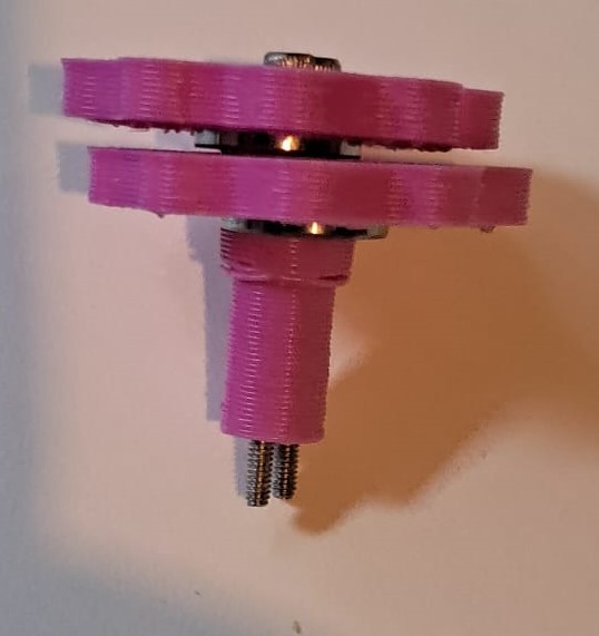
Prototype #1
3D Prints
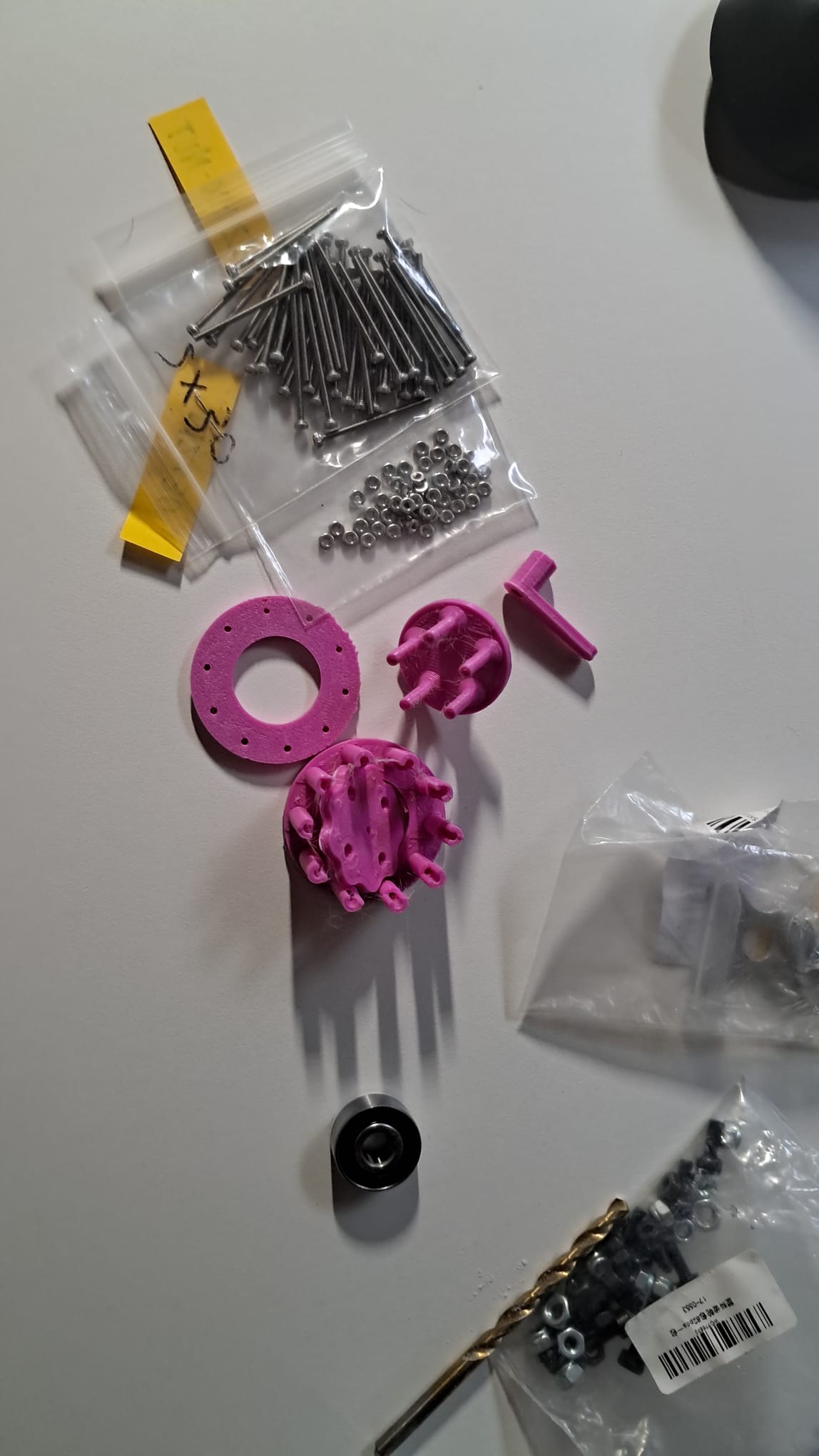
In Action (barely)
Main problems with this prototype:
- The cycloidal disk can be heard grinding against the rollers on the fixed plate even though the disk was toleranced for clearance.
- The 1mm eccentricity of the disk with relation to the center of fixed part of the drive and was tested for next.
Prototype #2
For the next iteration of the prototype, adjustments were made in CAD as follows:
- 3 sets of cycloidal disks were printed with each cycloidal profile shaving 0.1mm from the last, in addition to larger clearance tolerances;
- 6 shafts were printed with each diameter increasing by 0.1mm from 1.0mm to 1.5mm;
- the rollers were scrapped and replaced by a cycloidal profile on the fixed housing.
3D Prints
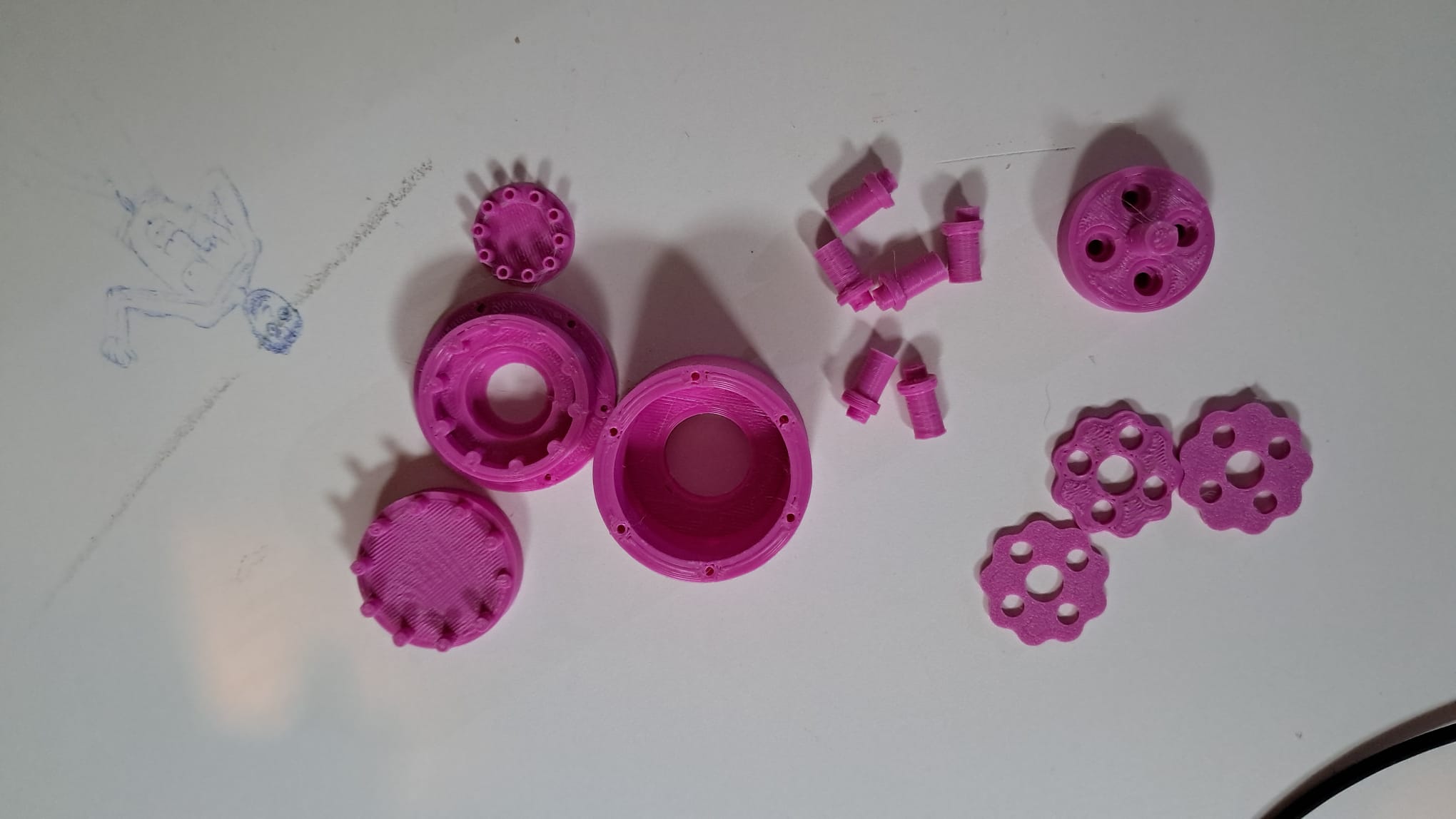
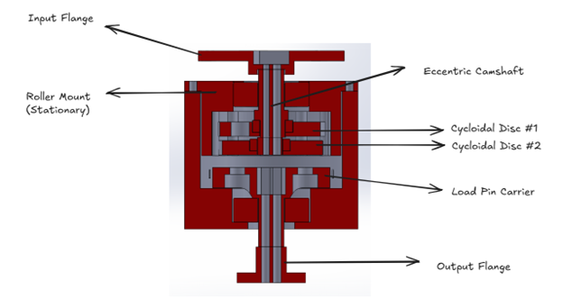
CAD Mechanism


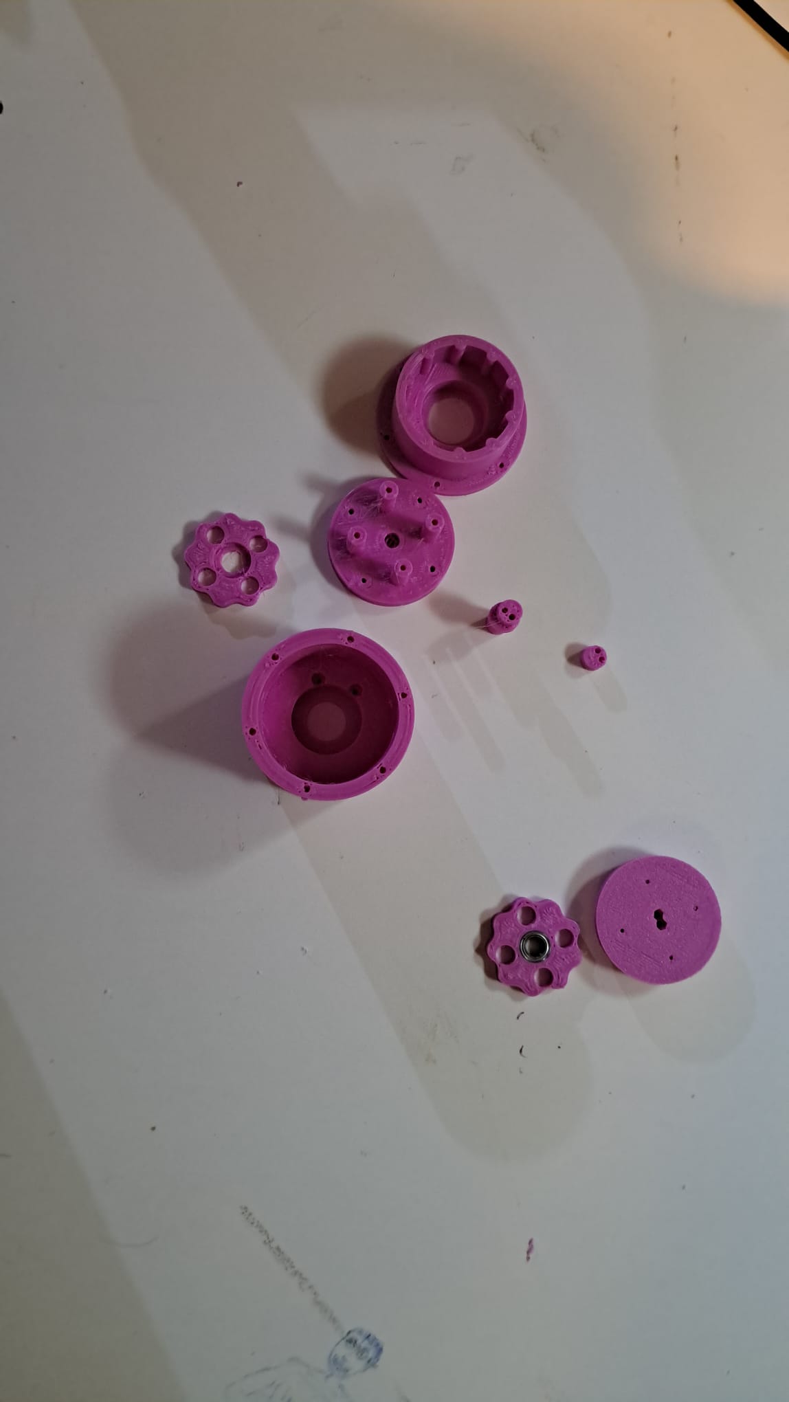
Disassembly
9:1 Reduction
Having a single cycloidal disk introduces a lot of vibrations into the drive, so a general recommendation is to have a second cycloidal disk with its cam offset by 180 degrees. This in turn halves the load pin diameter! The third prototype was designed with these changes in mind.
Prototype #3
3D Prints
Assembled Camshaft
After assembly, the drive was tested for friction, noise and cycle tested for wear. The load during testing was 2 kgs at 1.75cm from the drive’s center, resulting in a torque of 0.34 Nm which is slightly higher than the stall torques listed on the MN4004 BLDC website. This is still ~8x lower than the maximal output torque expected from the solo12 actuator (~2.7Nm), but is closer to torque values during resting / trotting gait.
First, to verify the working of the drive, it was hand driven:
Then the drive was tested with a 1000 KV BLDC running at 12V:
Finally, using a drill, it was tested at high speed and the aforementioned torque:
After about an hour of intermittently cycling with the drill, the 3D printed discs started wearing at the profile, forming ABS powder and a lot of backlash is observed in the drive.
Current drive cost:
| Parts | Cost (CAD) | Quantity |
|---|---|---|
| ABS | ~1.6$ | 79 grams |
| 1603-2RS Bearing | 3.2$ | 2 |
| M2x30mm | 0.8$ | 10 |
| M2 Hex Nut | 0.36$ | 10 |
| MR128ZZ | 0.4$ | 2 |
| Total Cost: | 6.36$ |
Conclusion
This exercise helped the mechanical team better understand the long term drawbacks of a 3D printed drive at the aforementioned scale. The cycloidal drive quickly wears down and loses alot of its favorable properties. Quick way to reduce friction in the drive would be to replace the lobes of the cycloidal profile against which the disk moves with rollers but this brings with it additional hardware costs. One could also have multiple cycloidal disks offset by smaller angles but this would keep decreasing the load pin diameter to a point where it would be impossible for the pins to be structural!
Further explorations into more accessible alternatives to the dual-stage timing belt reduction will also be conducted in the near future, check back for bi-weekly updates. :)